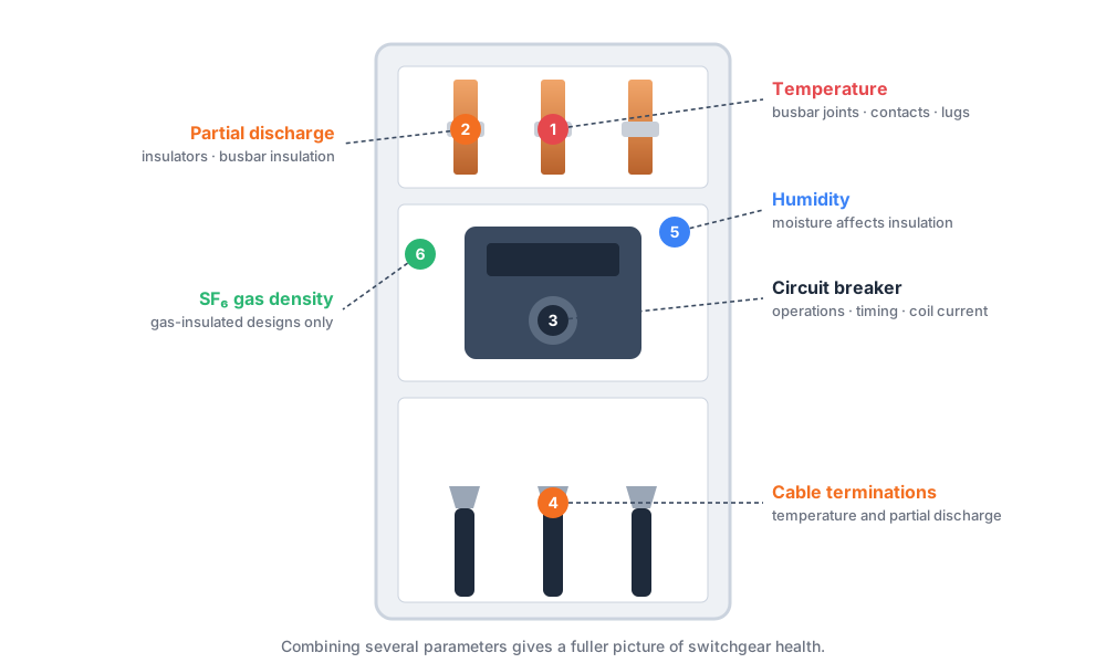
High voltage switchgear condition monitoring is the practice of measuring parameters that show how switchgear is aging or developing faults, either continuously or at set intervals. Switchgear carries load current through many bolted joints, contacts and insulated parts, and problems in these areas often build up slowly before they cause an outage. Commonly monitored parameters include contact and busbar temperature, partial discharge, circuit breaker operation, humidity and, in gas-insulated designs, gas condition. Trend data from these measurements helps maintenance teams decide when to inspect, service or plan an outage. Online monitoring is most useful on critical assets, where waiting for the next scheduled inspection leaves a long gap without visibility.
- Switchgear condition monitoring tracks temperature, partial discharge, breaker condition and environmental factors to show developing problems.
- Temperature monitoring at busbar joints, cable terminations and breaker contacts is one of the most common measures, because loose or degraded connections heat up.
- Partial discharge monitoring addresses insulation condition, while breaker monitoring addresses mechanical condition.
- Online monitoring adds continuous visibility and alarms between inspections, but it does not remove the need for periodic inspection and testing.
- The right scope depends on voltage class, switchgear design, site criticality and whether the project is a retrofit or a new installation.
What Is High Voltage Switchgear Condition Monitoring?
High voltage switchgear condition monitoring is the collection and evaluation of data that reflects the health of switchgear components. A switchgear monitoring system turns sensor readings into trends and alarms that maintenance teams can act on.
Switchgear condition monitoring can cover:
- Temperature
- Partial discharge
- Breaker mechanical condition
- Gas condition where applicable
- Humidity and environment
- Contact condition
- Cable termination condition
No project needs every item. The selection follows the design, the risks and the consequence of an outage.
Why Is Switchgear Condition Monitoring Important?
Most switchgear problems develop over time. Regular inspection catches some, but a defect can progress between visits. Common risks include:
- Loose electrical connections that raise contact resistance and heat.
- Contact overheating from wear, contamination or poor contact pressure.
- Insulation deterioration from aging, contamination or stress.
- Partial discharge that gradually damages insulation.
- Breaker wear in the operating mechanism and contacts.
- Cable termination defects that cause heating or discharge.
- Moisture or environmental stress from humidity, dust or condensation.
What Parameters Are Monitored in High Voltage Switchgear?
| Monitoring Parameter | Typical Location | Why It Matters | Common Monitoring Method |
|---|---|---|---|
| Temperature | Busbar joints, contacts, cable lugs | Shows abnormal heating from poor connections | Fiber optic, wireless or infrared sensors |
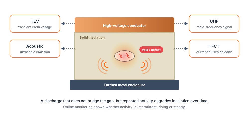
| Partial discharge | Insulators, cable compartments, busbar insulation | Indicates insulation stress or defects | UHF, TEV, acoustic or HFCT sensors |
| Circuit breaker condition | Breaker and operating mechanism | Shows mechanical wear and operation health | Timing, coil current and counter monitoring |
| Busbar connections | Joints and bolted connections | High-current joints are common hotspot sites | Temperature sensors at the joint |
| Cable terminations | Cable compartment | Termination defects cause heating or discharge | Temperature and PD sensors |
| Humidity | Inside compartments or room | Moisture affects insulation performance | Humidity and environment sensors |
| SF6 gas condition (where applicable) | Gas-insulated compartments | Gas pressure and density relate to insulation and safety | Gas density or pressure monitoring |
SF6 monitoring applies only to gas-insulated designs. Air-insulated and vacuum designs do not use it.
Switchgear Temperature Monitoring
Switchgear temperature monitoring measures heat at the places where current passes through connections. Switchgear thermal monitoring typically covers:
- Busbar joints
- Cable terminations
- Breaker contacts
- Bolted connections
- Switchgear compartments
Local hotspots can appear before any visible damage. A joint with rising resistance heats up gradually, and the rest of the panel may look normal. Switchgear hotspot monitoring at the joint itself gives earlier and more specific information than a compartment reading.
Fiber Optic Temperature Monitoring for Switchgear
Point-type fluorescent fiber optic temperature sensors are widely used in high-voltage and high-EMI switchgear. Each sensor measures temperature at one location, so it is placed at a chosen hotspot. This is different from distributed temperature sensing, which measures along a length of fiber.
- Electrical isolation. The probe is made of dielectric material, which suits placement close to energized parts.
- Immunity to electromagnetic interference. The optical signal is not affected by strong electric and magnetic fields.
- Point temperature measurement. Sensors sit directly on joints, contacts or terminations.
- Multi-channel monitoring. One controller can serve several measurement points.
- Local alarms. Alarm outputs can trigger warnings at the panel or control room.
- PLC and SCADA integration. Data can be passed to supervisory systems.
Busbar Temperature Monitoring
Busbar temperature monitoring looks at the parts of the busbar system that carry the highest current density or rely on mechanical connection. Typical monitored points are:
- Busbar joints
- Bolted connections
- Contact points
- High-current connection areas
Busbar hotspot monitoring helps because a joint can degrade slowly through loosening, oxidation or thermal cycling. Placing a sensor on the joint gives a direct reading, and trend data shows progressive heating. For the busbar-specific solution, see busbar monitoring.
Switchgear Partial Discharge Monitoring
Partial discharge in switchgear is a localized electrical discharge in insulation that does not bridge the gap between conductors. Repeated activity can degrade insulation over time.
Where Can It Occur?
- Solid insulators and spacers
- Cable terminations and joints
- Busbar insulation
- Voids, contamination or sharp electrode points
Why Monitor It?
PD activity can show insulation problems before a failure. Switchgear partial discharge monitoring adds trend data that a single test cannot give.
Online Monitoring vs Periodic Testing
Periodic testing shows PD at the test date. Online switchgear monitoring records activity over time, which helps show whether activity is intermittent, rising or steady. Interpretation still needs engineering review, since noise can resemble PD.
Circuit Breaker Monitoring
Circuit breaker monitoring follows the mechanical and electrical behavior of the breaker. Typical items are:
- Operation count, which relates to wear.
- Contact condition, estimated from available data.
- Operating mechanism condition.
- Opening and closing time.
- Coil current, which reflects mechanism behavior.
- Mechanical wear indicators.
- Breaker temperature where relevant.
Changes over time matter more than a single value.
Cable Termination and Connection Monitoring
Cable compartments are a frequent source of heating and insulation problems. Monitoring covers:
- Cable terminations
- T-connectors
- Cable compartments
- Cable joints inside switchgear
- Abnormal heating near connection points
Temperature monitoring picks up heating from poor connections, and PD monitoring picks up insulation activity at terminations. Both can apply to the same compartment.
Online Switchgear Monitoring vs Periodic Inspection
Online monitoring and periodic inspection serve different purposes. Online systems add continuous visibility, and inspections add hands-on checks that sensors cannot do. This is not an either-or choice, and online monitoring does not eliminate inspection.
| Item | Online Monitoring | Periodic Inspection |
|---|---|---|
| Monitoring frequency | Continuous or frequent | At scheduled intervals |
| Real-time visibility | Yes, depending on system | No |
| Alarm capability | Available | None between visits |
| Temperature trending | Ongoing | Limited to inspection dates |
| PD trending | Ongoing, if PD sensors are installed | Limited to test dates |
| Manual labor | Lower for routine data | Higher |
| Fault development between inspections | Visible in the data | May go unseen |
| SCADA integration | Possible | Not applicable |
| Typical use | Critical switchgear and hard-to-access sites | All switchgear, as routine practice |
A switchgear condition monitoring system extends what maintenance teams can see. It still relies on inspection, cleaning, torque checks and testing.
High Voltage vs Medium Voltage Switchgear Monitoring
High voltage switchgear monitoring and medium voltage switchgear monitoring share the same principles, but scope differs. It depends on:
- Voltage class: higher voltage raises insulation stress and safety demands.
- Switchgear design: compartment layout affects sensor access.
- Insulation type: air, gas or solid insulation changes the relevant parameters.
- Breaker type: vacuum, SF6 or air breakers have different monitoring needs.
- AIS or GIS construction: GIS may add gas monitoring and internal PD sensing.
- Site criticality: importance of the load affects how much monitoring is justified.
Medium-voltage panels often use temperature monitoring as a core measure, with PD added where risk is higher.
Common Switchgear Hotspot Locations
- Busbar joints. Bolted joints can loosen or oxidize, raising resistance.
- Breaker contacts. Contact wear and pressure changes increase heating.
- Cable lugs. Poor crimping or loose bolts cause local heat.
- Cable terminations. Termination defects can produce heat and discharge.
- Disconnecting contacts. Repeated operation and contamination affect contact quality.
- Bolted electrical connections. Thermal cycling can reduce clamping force.
- High-current connection points. Higher current makes any resistance increase more significant.
In each case, heat is a symptom of higher resistance or poor contact, and it grows gradually. Trend data helps show that progression.
How Does a Switchgear Monitoring System Work?
The typical flow is:
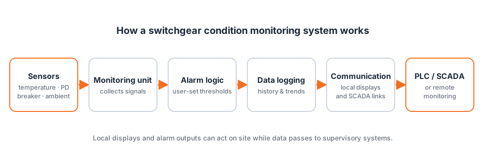
Sensors → monitoring unit → alarm logic → data logging → communication → PLC, SCADA or remote monitoring
A switchgear condition monitoring system can combine several functions:
- Fiber optic temperature sensors
- PD sensors
- Breaker monitoring inputs
- Environmental sensors
The monitoring unit collects signals, applies alarm settings chosen by the user and stores data. Communication then passes data and alarms to local displays or supervisory systems.
How to Select Sensors for Switchgear Condition Monitoring
- Monitoring parameter. Temperature, PD, breaker or environment.
- Switchgear voltage level.
- Measurement point. Joint, contact, termination or compartment.
- Electromagnetic environment. Strong fields favor sensors immune to interference.
- Insulation requirements. Sensors near live parts need suitable isolation.
- Number of channels.
- Temperature range needed at the measurement point.
- Communication interface.
- Local display requirements.
- Alarm output.
- SCADA integration.
- Retrofit or new installation. Retrofit access and space limit options.
Check sensor data sheets and confirm requirements with the supplier, since capabilities vary by product.
Switchgear Monitoring for Substations and Industrial Facilities
- Utility substations: reliability of supply and reduced site visits.
- Industrial plants: protection of continuous processes.
- Renewable energy substations: variable load and remote locations.
- Data centers: supply continuity is essential.
- Mining: harsh conditions and difficult access.
- Oil and gas: critical supply and safety needs.
- Rail systems: service continuity for traction power.
- Power generation facilities: auxiliary and station switchgear.
Electrical switchgear monitoring in these sites adds visibility where outages are costly or access is limited.
How Switchgear Condition Monitoring Supports Preventive Maintenance
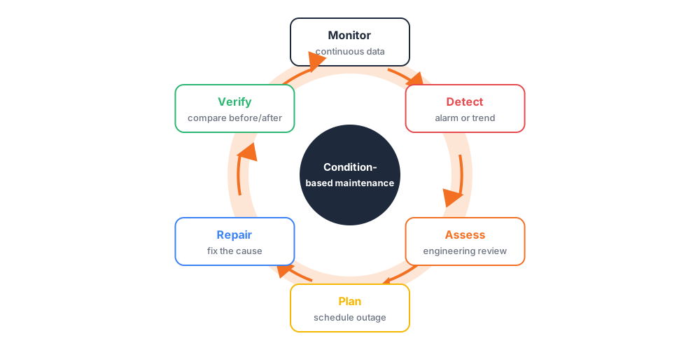
Trend data helps teams move from fixed schedules toward condition-informed maintenance. It can help identify:
- Progressive heating at a joint or contact.
- Repeated PD activity in a compartment.
- Breaker wear shown by changing operating times.
- Abnormal connection behavior, such as heating that follows load.
- Environmental issues, such as rising humidity.
Monitoring does not predict every failure. It gives earlier information so teams can inspect, plan outages and prioritize work.
Switchgear Condition Monitoring vs Traditional Inspection Methods
| Method | What It Provides | Limitation |
|---|---|---|
| Infrared inspection | Thermal image at inspection time | Snapshot, needs line of sight and load |
| Manual thermal inspection | Spot temperature checks | Periodic, depends on access |
| Scheduled shutdown inspection | Thorough hands-on check | Needs outage, infrequent |
| Portable PD testing | PD data at test time | Snapshot only |
| Contact resistance testing | Direct resistance measurement | Needs de-energized equipment |
| Online condition monitoring | Continuous trends and alarms | Limited to instrumented points |
The methods complement each other. Online monitoring shows change between visits, and periodic testing verifies and adds detail.
How to Select a High Voltage Switchgear Condition Monitoring System
- Switchgear voltage class.
- AIS or GIS.
- Number of panels.
- Temperature monitoring points per panel.
- PD monitoring requirement.
- Breaker monitoring requirement.
- Number of channels.
- Communication protocol.
- Local display requirement.
- SCADA integration.
- Alarm requirements.
- Installation method.
- Retrofit or new project.
The final monitoring configuration should match the actual switchgear design and project requirements. To discuss a project, send the voltage class, panel count and monitoring needs through our contact page.
Conclusion
High voltage switchgear condition monitoring gives maintenance teams continuous data on temperature, insulation activity and breaker behavior. Used together with regular inspection and testing, it reduces blind spots between visits. Start with the risks that matter most for your switchgear, choose sensors that suit the environment and size the system to the design and criticality of the site.
FAQ
It is the measurement and evaluation of parameters such as temperature, partial discharge and breaker condition to show how switchgear is aging or developing faults. It can be continuous through online systems or periodic through inspection and testing.
Common parameters are temperature at joints and contacts, partial discharge, breaker operation data, humidity and, for gas-insulated designs, gas condition. The right set depends on switchgear design, voltage class and site criticality.
Typical points are busbar joints, breaker contacts, cable lugs and terminations, disconnecting contacts and bolted connections. Final positions depend on panel design, access and safe clearances, so follow the manufacturer’s guidance.
Temperature monitoring detects heating, mainly from poor connections or contact problems. Partial discharge monitoring detects electrical discharge activity in insulation. They address different failure mechanisms and often complement each other.
Yes, many systems can pass data and alarms to PLC or SCADA using common communication interfaces. Confirm the protocol and signal list with the supplier for your project.
Online monitoring records data continuously or frequently and can raise alarms between visits. Periodic inspection gives hands-on checks at set times. Most maintenance programs use both.