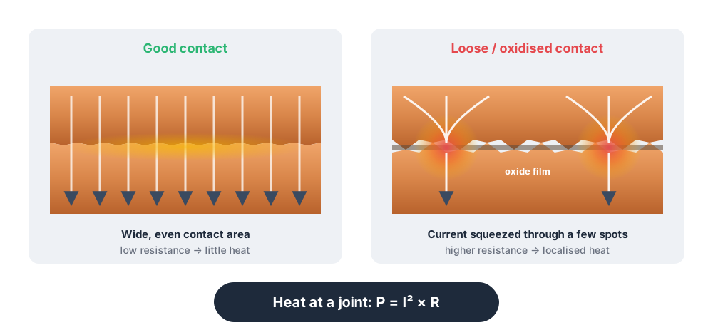
Abnormal heating at electrical connections is often associated with loose connections, oxidized contact surfaces or worn contacts. These conditions increase contact resistance, generating more heat as current flows. Localized overheating can occur even without an overload.
From cable terminations to circuit breaker contacts, connection interfaces are useful temperature measurement points. Understanding why contact quality deteriorates, then comparing temperature changes with the equipment supplied, helps maintenance teams schedule checks earlier.
Why do connections loosen, oxidize or wear?
Connection condition depends on installation quality, operating conditions and the environment. Poor crimping or fastening can prevent good contact from the outset. Vibration during operation and repeated thermal expansion and contraction as loads change can also gradually loosen connections.
Environmental exposure can oxidize or corrode contact surfaces, while contacts that open and close frequently can wear with use. Reduced effective contact area or an oxide layer that impedes conduction makes localized heating more likely. Both new and long-serving equipment can therefore have connection problems; age alone is not a reliable basis for assessment.
How does connection overheating affect equipment and the power supply?
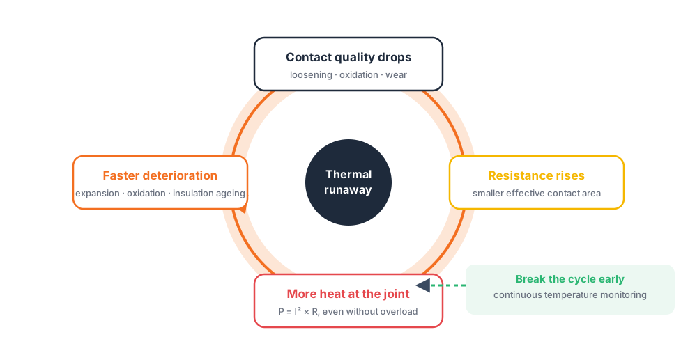
Sustained overheating can accelerate deterioration of connections and nearby insulation, damage the joint and even interrupt the power supply. The impact may extend from one device to several on the same supply path. If critical processes are involved and redundancy is unavailable, production may be interrupted.
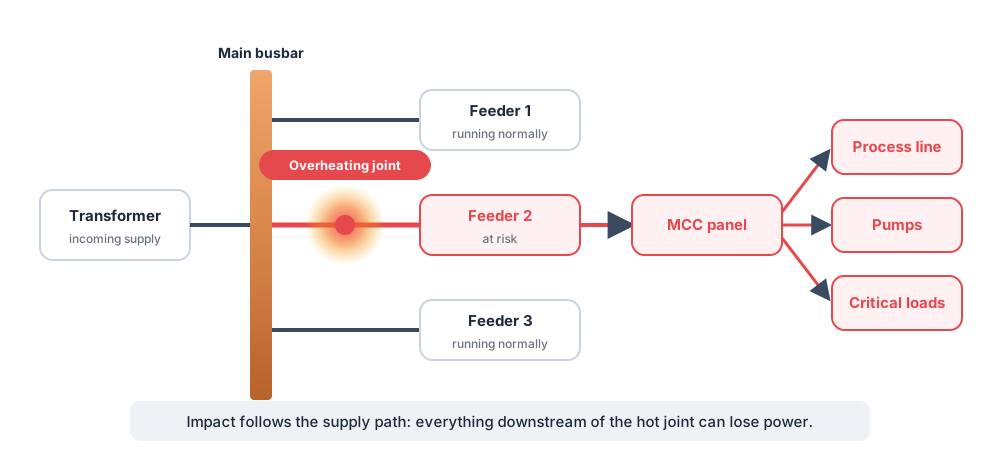
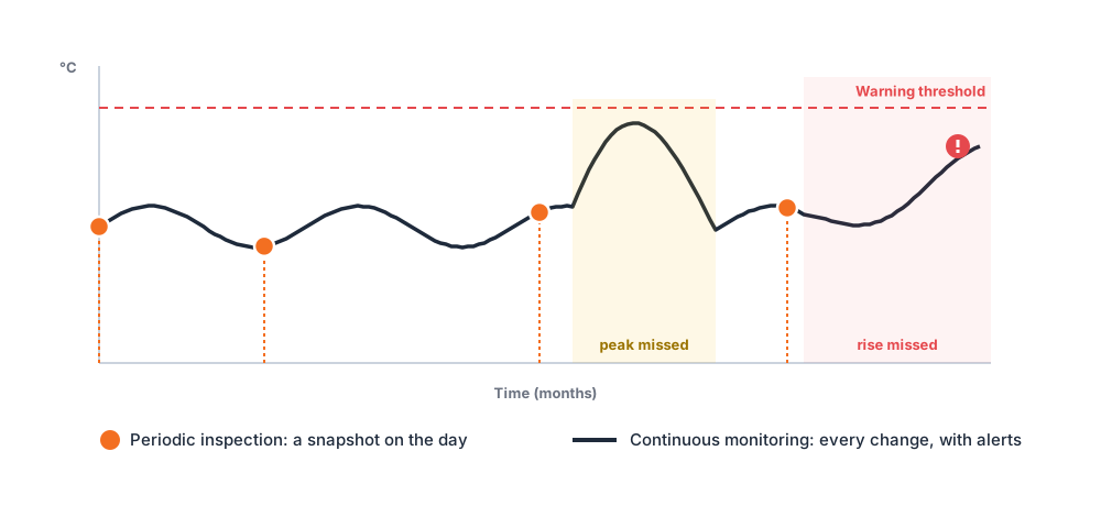
When assessing an abnormal connection, identify the equipment it supplies as well as tracking its temperature. Continuous monitoring can help teams notice rising temperatures before visible changes appear, then plan inspection and maintenance according to the potential supply impact.
Causes of heating and inspection priorities for five connection types
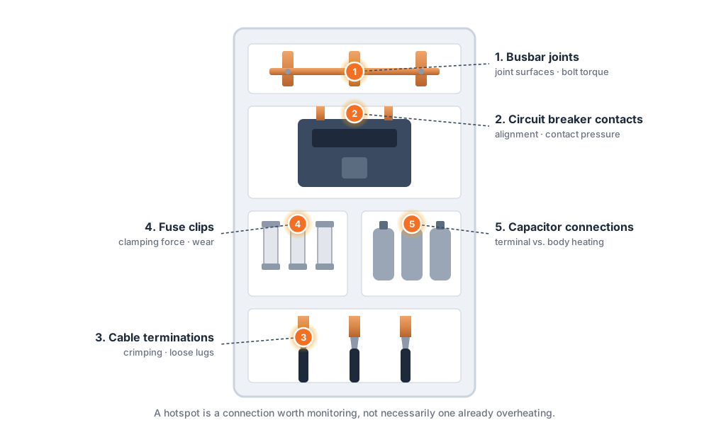
The table summarizes possible heating causes and inspection priorities for five common connection types. Here, a hotspot means a connection worth monitoring, not a point that is necessarily already overheating.
| Hotspot | Possible heating mechanism | Inspection focus |
|---|---|---|
| Cable termination | Poor crimping or a loose terminal increases contact resistance | Contact and fastening condition at the joint |
| Busbar joint | Deteriorated joint surfaces or loose fasteners create localized heating | Joint surfaces, fasteners, and adjacent connections |
| Circuit breaker contact | Poor positioning, worn contacts, or insufficient pressure impair contact quality | Contact alignment and pressure-maintaining components |
| Capacitor connection | Poor contact at terminals or supply connections produces heat | Distinguish connection faults from capacitor-body problems |
| Fuse clip | Wear reduces clamping force or effective contact area | The interface between the fuse and its clip |
Busbar joints: check joint surfaces and fastening
Oxidation, deterioration or loose fastening at a busbar joint can impair electrical contact. When a localized temperature rise is found, include that joint and adjacent connections in the inspection and identify the equipment they supply.
Circuit breaker contacts: check alignment and contact pressure
Breaker contact quality depends on alignment and contact pressure. Inspection should cover contact wear and the components that maintain clamping force.
Capacitor connections: distinguish connection faults from body faults
Localized heating at capacitor terminals and connecting busbars should be assessed separately from capacitor-body faults. Locating the heat helps focus inspection on terminals, joint surfaces, or fasteners.
Fuse clips: include the clamping interface in the inspection
A fuse in good condition does not establish that its clips are making good contact. Worn clips or insufficient clamping force can still cause localized heating, so inspections and temperature checks should include the interface between the fuse and its clip.
Amptronics Passive Wireless RFID Temperature Monitoring Solutions
Amptronics provides passive wireless RFID temperature monitoring solutions that combine battery-free sensors, antennas, and readers to collect temperatures at cable terminations, busbars, and circuit breaker contacts. This helps maintenance teams monitor concealed connections and fill data gaps between inspection rounds.
For connections requiring ongoing tracking, Amptronics supports fixed installations with temperature displays, historical records, and alerts, depending on configuration. Maintenance personnel can locate abnormal connections, track temperature rises, and prioritize connections that supply critical equipment or repeatedly heat up.
Related products and solutions: Industrial temperature monitoring solutions.
Contact us to discuss a connection temperature monitoring configuration suited to your equipment and maintenance needs.
Contact usFAQ
Consider the temperature rise, whether the anomaly recurs, and the equipment and redundancy associated with the connection. Compare temperatures alongside the load and historical records, rather than setting inspection priorities solely by the highest reading on one occasion.
RFID sensors return temperatures from selected connections through antennas and readers without requiring direct sight of the sensors. Metal partitions affect RF transmission, so antenna placement must account for the compartments inside the equipment.
A loose connection is one possible cause. Poor crimping, deteriorated contact surfaces, and insufficient clamping pressure can also produce localized heating. Temperature data helps locate an anomaly, while load, historical trends, and on-site inspection are needed to establish its cause.
Fixed monitoring captures temperature changes between inspection rounds, with historical records and alerts depending on configuration. This helps personnel identify heating that was not present at the time of an inspection.