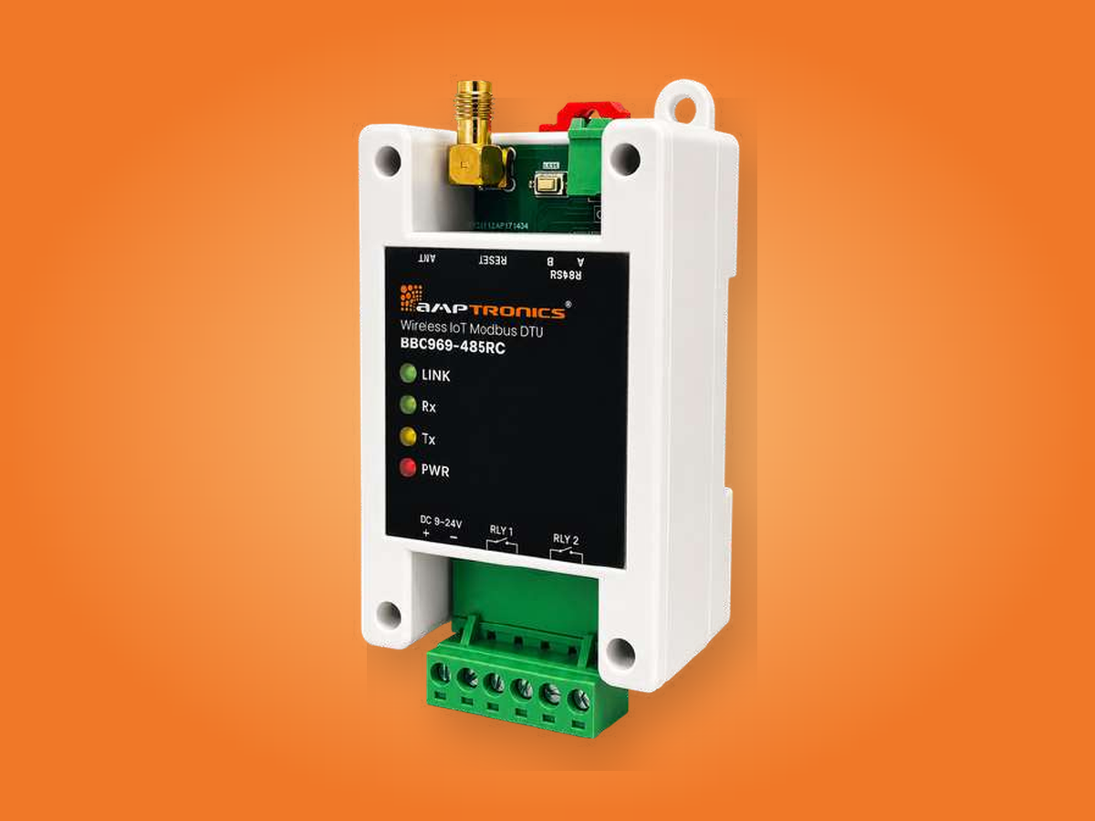
BBC969-485RC
Wireless IoT Modbus DTU for Busbar & Switchgear MonitoringThe receiver at the core of the Wireless Busbar Temperature Monitoring System (WBTMS). It collects temperature and battery data from busbar, humidity and bus duct sensors, drives two alarm relays, and passes everything to your PLC or SCADA over Modbus RTU.
- Supports up to 60 BBS350 busbar sensors and 28 RHT / bus duct sensors
- Modbus RTU over RS485, with selectable baud rate and parity
- Two dry-contact relays for temperature and humidity thresholds
- AES-128 encrypted wireless link, robust in electrically noisy panels
Continuous busbar and bus duct temperature monitoring
Excessive temperature in a busbar or bus duct is often the first sign of overloading, deteriorating connections or rising contact resistance. Left undetected, prolonged overheating degrades insulation and increases the risk of faults, short circuits, equipment damage and fire.
The BBC969-485RC reliably captures and processes RF signals from busbar temperature sensors, humidity sensors and bus duct temperature sensors within a 10 m operating range. It collects real-time temperature values and sensor battery status, and its robust RF reception keeps data flowing even in electrically noisy environments.
Built for installation inside control panels, it fits easily into existing systems. Two relay outputs act independently on temperature and humidity thresholds and can drive external alarms, annunciators or automation systems.

Simple setup through a built-in web interface
- 1Enable Wi-FiPress the Reset switch once. The Link LED confirms the receiver's Wi-Fi is on.
- 2Configure the deviceConnect from a laptop browser and set the country frequency, channel, number of sensors, operation mode and relay limits.
- 3Register sensorsEnter the UID printed on each sensor label, then restart the receiver.
- 4Join the networkDouble-press Reset to open join mode and switch on each sensor. The Join Status page shows each one in green once it's connected.
- 5MonitorLive temperature, humidity, battery voltage and signal strength (RSSI) appear in the web interface and over Modbus.
| General | |
|---|---|
| Model number | BBC969-485RC controller |
| Max. sensors per controller | Spread spectrum technology, 60 BBS350 & 28 RHT sensors |
| Mounting | DIN rail |
| Installation location | Bus ducts, electrical panels, switchgear, MCC panels, control panels |
| Enclosure | ABS plastic |
| Operating voltage | 9–28 V DC |
| Dry contact relays | 2, Common – NO |
| Communication | |
| Max. reception range | 10 m |
| Frequency | 865–926 MHz (IN/EU/SA/ME 865–868, US/CA/AU/NA 920–923, ID/VA/LA/HK 923–925) |
| Antenna | SMA antenna with magnetic base, 2 m cable |
| Communication protocol | Modbus RTU over RS485 |
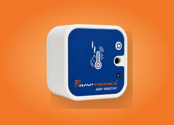
| Supported sensors | BBS350BT, BBS350CT, AMP-WRHTC, AMP-WM2THC |
| Data encryption | AES-128 |
| Configuration | Built-in Wi-Fi web interface |
| Mechanical | |
| Dimensions (L × W × H) | 100 × 55 × 33 mm |
| Weight | 100 g |
Receiver pin 6 (A+) → Modbus A+
Receiver pin 7 (B−) → Modbus B−
Follow proper termination and grounding practice for reliable communication.
Baud rate 4800 to 115200 (default 9600) · 7 or 8 data bits · parity none, odd or even · 1 or 2 stop bits · function code 03 (read holding registers)
| Device settings | 0–18 Device ID, baud rate, parity, country, channel, sensor counts, relay limits and status, sensor settings |
|---|---|
| Busbar sensor temperature | 100 onwards One register per sensor (100 = sensor 1, 101 = sensor 2 …) |
| Busbar sensor battery | 300 onwards One register per sensor (300 = sensor 1 …) |
| RHT & bus duct sensors | 500 onwards 4 registers per sensor: ambient temp, humidity, surface/duct temp, battery |
| Busbar sensor RSSI | 1000 onwards Signal strength per busbar sensor |
| RHT sensor RSSI | 1090 onwards Signal strength per RHT / bus duct sensor |

Value for every team that keeps power flowing
- Continuous visibility of critical electrical assets and connections
- Lower CAPEX and OPEX with less reliance on periodic thermography
- Less need for people to work near energised equipment
- Catch emerging thermal issues before costly failures and downtime
- Better asset performance, reliability and lifecycle ROI
- Extend asset life with condition-based maintenance
- No more manual checks at inaccessible connection points
- Move from reactive to proactive asset management
- Monitor connection temperatures accurately and spot anomalies early
- Make maintenance decisions on real-time data
- Continuously monitor critical connections and assets
- Detect temperature rise and compromised joints before they become critical
- Reduce the risk and cost of unplanned outages
- Get real-time alarms when thresholds are exceeded
- Improve reliability with constant visibility of infrastructure health
Sensors that connect to the BBC969-485RC
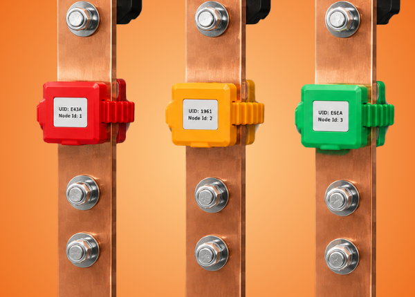
Battery-powered strap-on busbar sensor, up to 5 years of battery life.
View product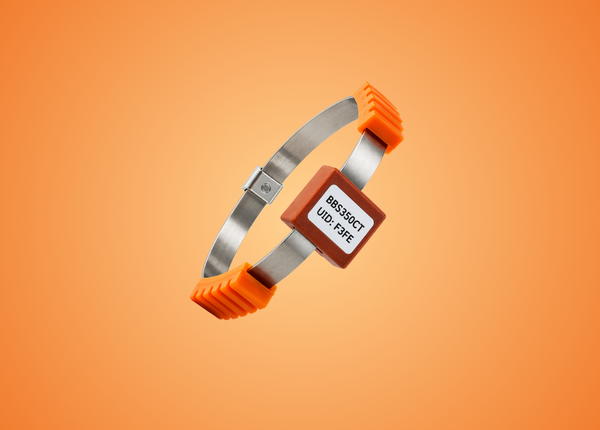
Wireless busbar temperature sensor with stainless-steel band clamp.
View product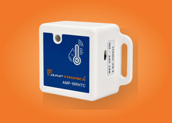
Bring busbar temperatures into your SCADA
Tell us about your panels and control system, and we'll plan the sensors, receivers and Modbus integration for your site.
Request a quote Download datasheet